Modeling muscles of
(biological) mice with Maya
Useful Links:
Adobe Photoshop
Quick Selection Tool: http://help.adobe.com/en_US/photoshop/cs/using/WSFD9BA8C5-31BA-4fec-81F3-CF04EE5295FCa.html
Layers: http://help.adobe.com/en_US/photoshop/cs/using/WSfd1234e1c4b69f30ea53e41001031ab64-78e3a.html
Painting: http://help.adobe.com/en_US/photoshop/cs/using/WSfd1234e1c4b69f30ea53e41001031ab64-780aa.html
Autodesk Maya
Polygon Modeling: http://download.autodesk.com/us/maya/Maya2012_Getting_Started/index.html?url=files/Modeling_a_polygonal_mesh_Introduction.htm,topicNumber=d28e6265
Subdivision Surfaces: http://download.autodesk.com/us/maya/Maya2012_Getting_Started/index.html?url=files/Modeling_a_subdivision_surface_Introduction.htm,topicNumber=d28e11833
Autodesk Mudbox
Painting: http://download.autodesk.com/global/docs/mudbox2012/en_us/index.html
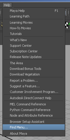
NOTE: Different Maya versions
may look different. However, you can use the Help system to find all the
functions. Specifically, for menu items, select Help->Find Menu… and you can
search for a menu command (shown below).
1. Project Setup
A project manages all the
resources. Since we are going to have many texture files as reference images,
project saves a lot of trouble of searching directories for texture files.
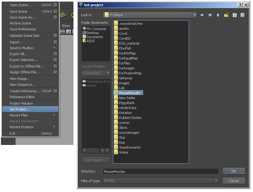
Select File->Set Project,
and choose the project folder.
NOTE: Though not necessary,
it is good to set a new “project” every time you start a new project.
2. Set coordinate system.
Maya’s default coordinate
system is Y-up, while a lot of other modeling tools use Z-up. Confocal data can also be seen as Z-up. So we also set
Maya’s coordinate system to Z-up for better compatibility.
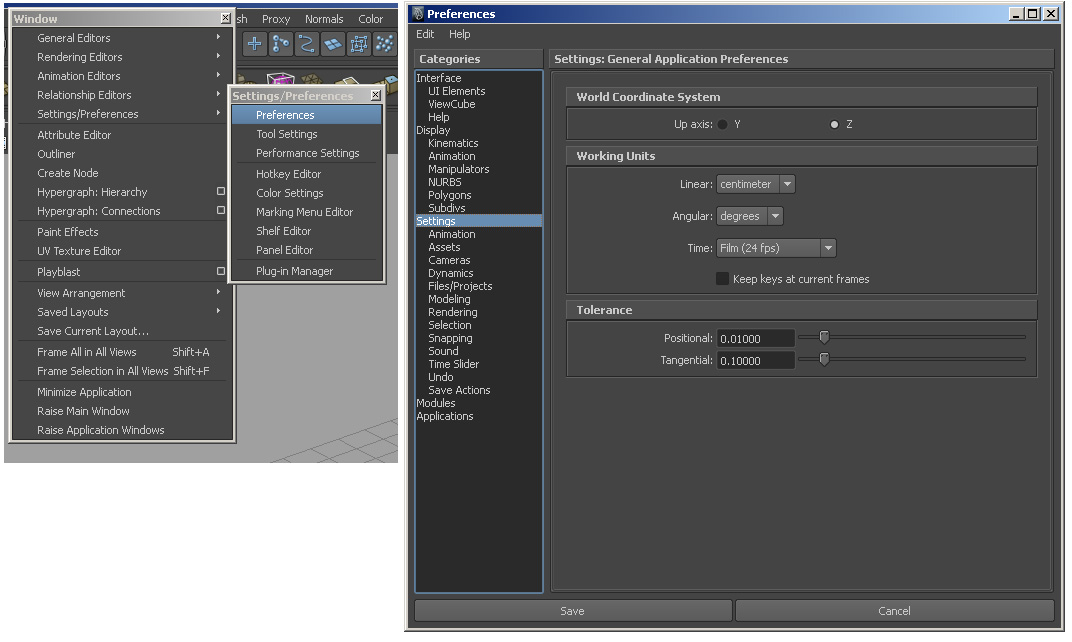
Select
Window->Settings/Preferences->Preferences. In the Preferences window, choose “Settings” from the
left column of categories, and select “Z” as the up axis under “World
Coordinate System” on the right.
NOTE: Do not forget to set
this setting back to “Y” when you work with your normal Maya projects. When you
see your human model in a prostrate position, probably it’s because of this
setting.
3. Visualizing volumetric confocal data in Maya
***This
step can be done via script, see end of step 3.5***
Different from 2D reference
images, which are used for modeling human characters, confocal
data are already 3D! We usually volume render 3D images, which Maya does not
have a good support. However, we can implement a basic volume renderer of our
own in Maya.
3.1
Create a polygon plane
NOTE:
If you still have not turned off interactive creation, maybe it is the time to
consider turning it off. Select Create->Polygon Primitives->and uncheck
“Interactive Creation”.
Select Create->Polygon Primitives->Plane. By default, a plane is created at world’s center,
with 10x10 subdivisions and 1x1 of size. You can set the settings before
creation by clicking the square to the right of the menu command. Setting
properties after creation is preferred.
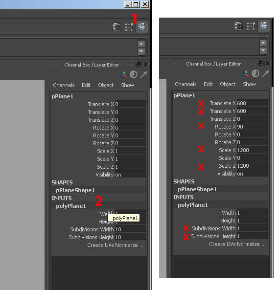
Show
the channel box if it is not shown. With the plane still selected, its
transformation properties are shown in the channel box. Expand the creation
properties of the plane by clicking on the name under “INPUTS”. We need to
change several settings. Basically we want the plane the same size as the confocal image slice, and one of the corners aligned with
the origin (0, 0, 0) with the plane itself in the positive XY quadrant. Now
check the perspective view to see if it is transformed as described above.
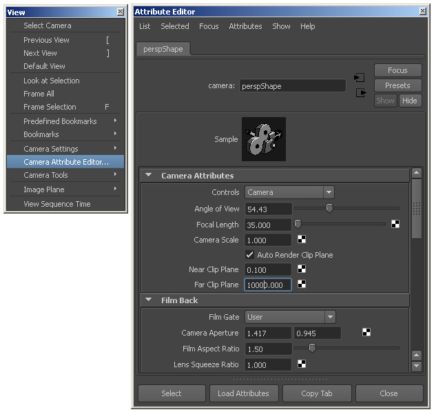
If
you cannot see the plane (you probably don’t, since it is too big now), in the
menu of perspective view, select View->Camera Attribute Editor…,
and then in the Attribute Editor, change camera’s “Far Clip Plane” to a larger
number.
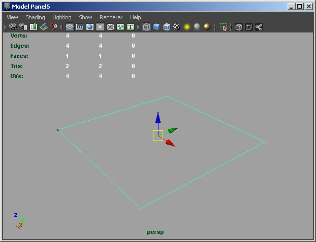
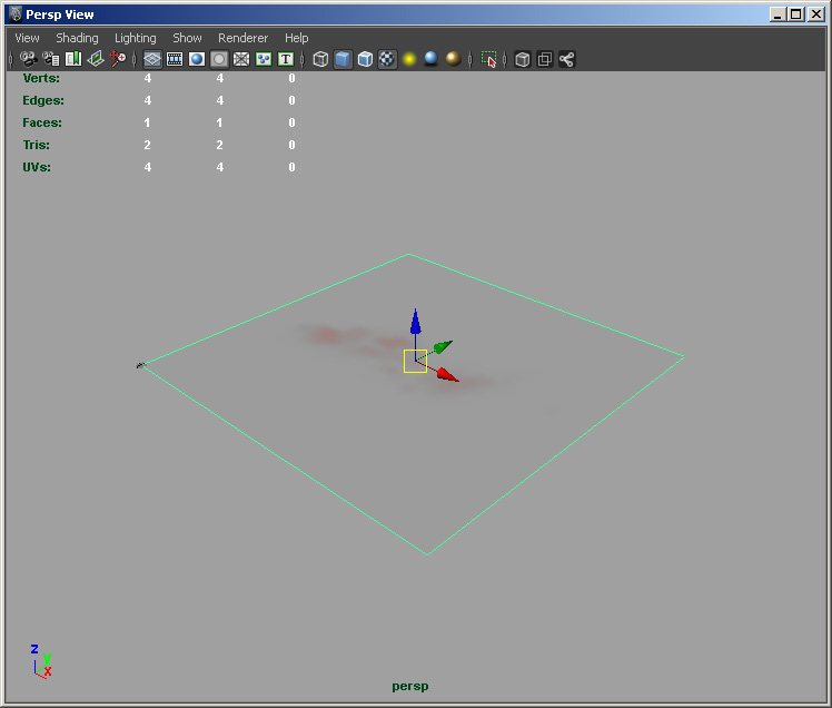
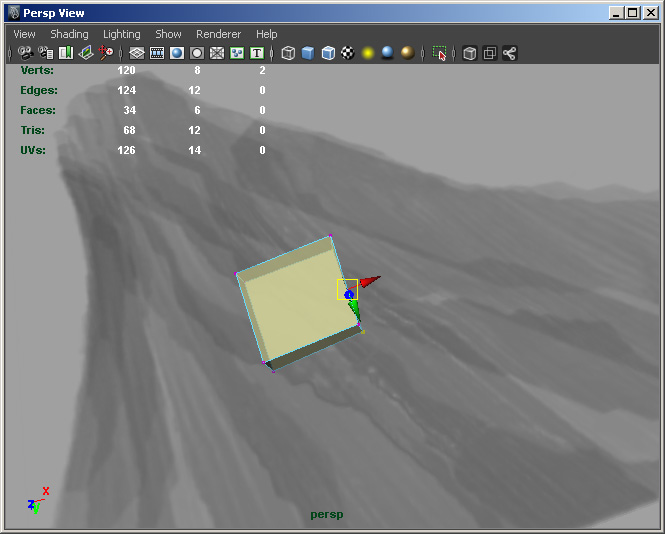
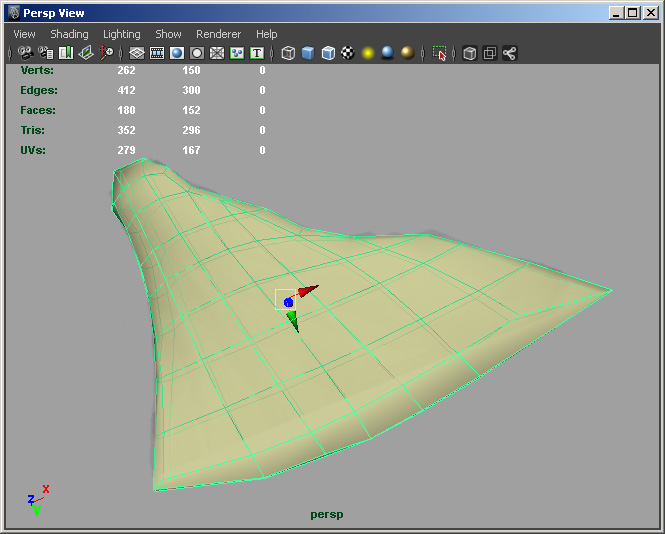
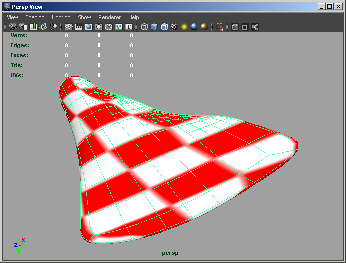
Press
“A” key when the mouse cursor is within the perspective view, and it should
look like the picture above.
3.2
Apply texture to the plane
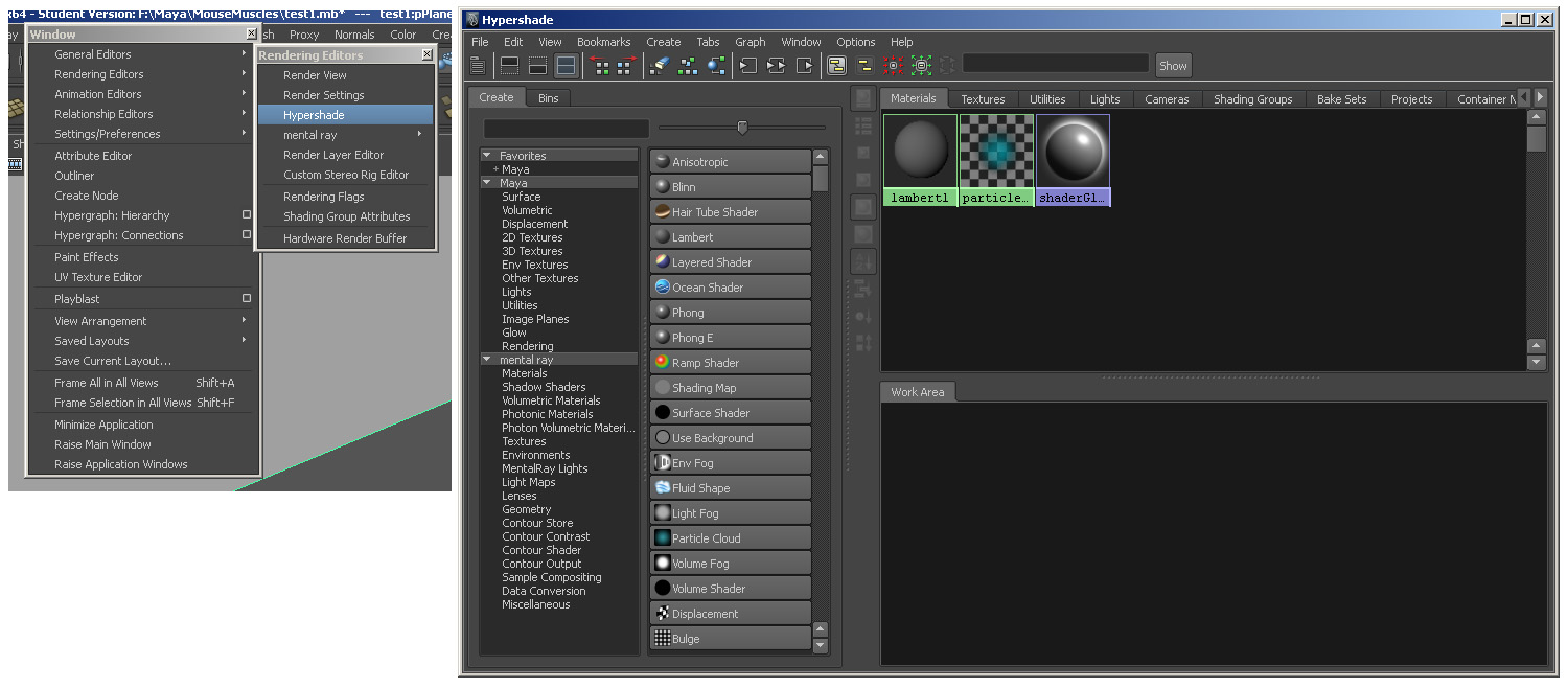
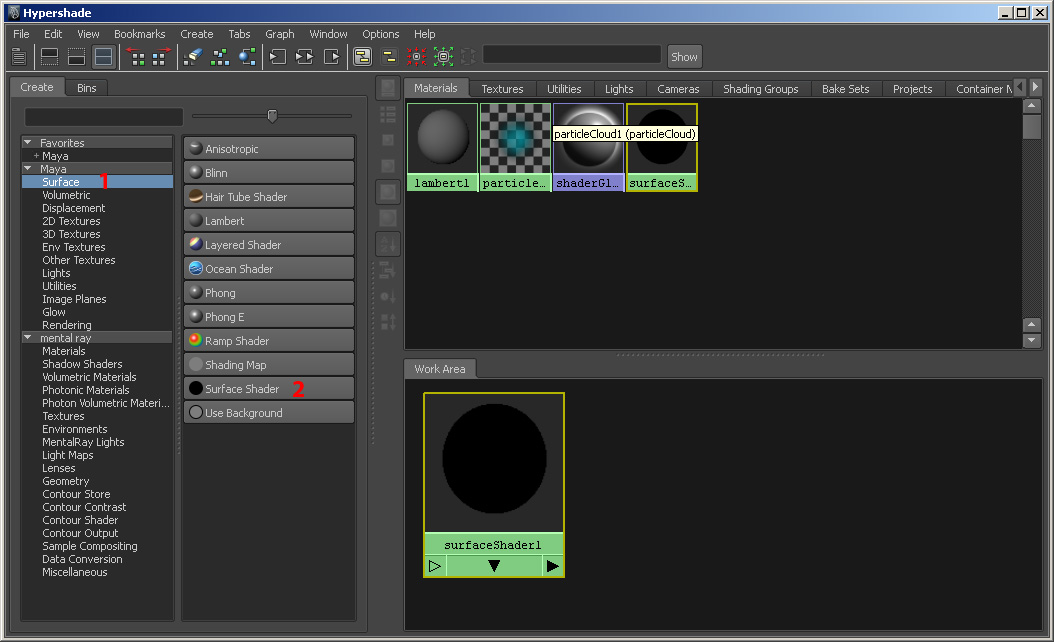
Select Window->Rendering Editors->Hypershade. In
Hypershade, create a “Surface Shader”
as shown below.
Double-click
the icon for the newly created surface shader, to
show its attribute editor.
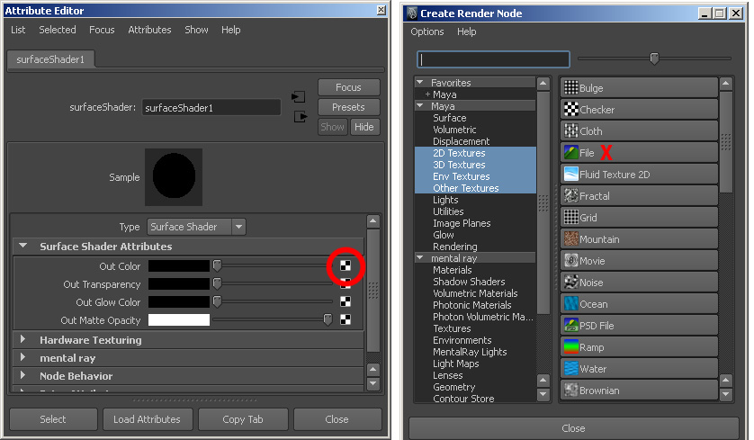
Click
the checkerboard icon to the right of property “Out Color”, and in the “Create
Render Node” window, select “File”.
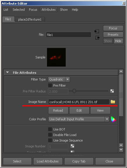
The
file node’s attribute editor will show automatically. Choose the confocal image of the first Z slice. Notice the image
file’s path is relative. That’s because we set the project earlier. If the path
is not relative, Maya may not find the proper file when the project is copied
from one computer to another.
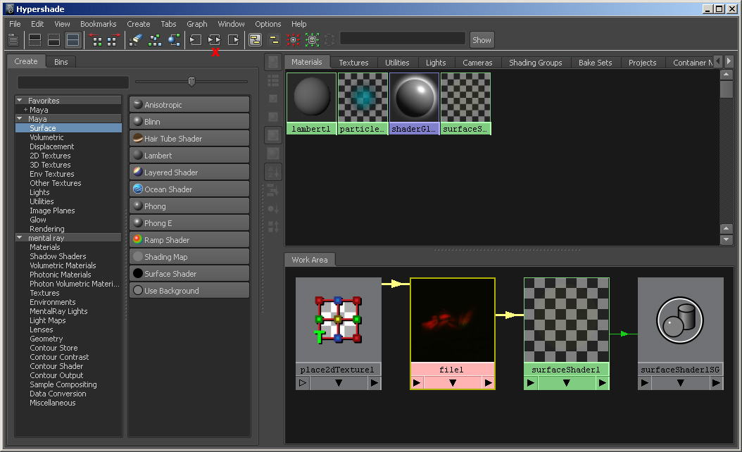
Now
click the Hypershader toolbar icon “Input and Output
Connections”, and the icons in the Work Area are clearly laid out.
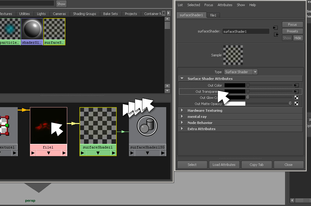
Select
the surface shader’s icon, and its attributes are
loaded. Middle-drag the file node’s icon to “Out Transparency” of the surface shader.
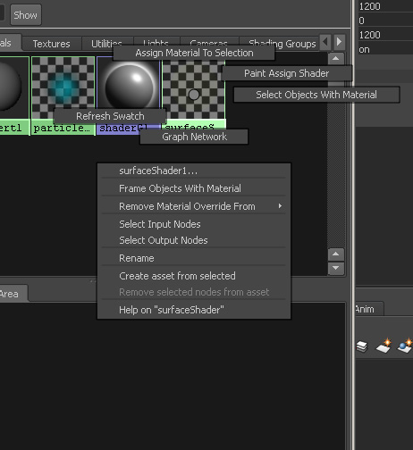
Select
the plane in the perspective view. In Hypershade,
right-click-and-hold on the surface shader icon until
the marking menu shows up. Without releasing the right mouse button, move mouse
cursor up and choose “Assign Material To Selection”. Hit “6” key when the mouse
cursor is in the perspective view. The perspective view should look like below.
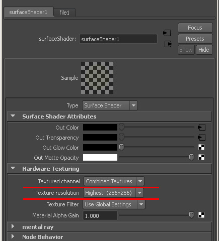
Select
the surface shader again. Under “Hardware Texturing”,
set “Texture channel” to “Combined Textures”, and “Texture Resolution” to
“Highest (256x256)”.
3.3
Duplicate the surface shader
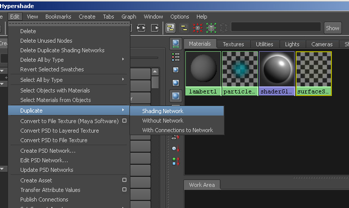
In Hypershade, select the surface shader
node if it is not selected. Then select Hypershade’s
menu Edit->Duplicate->Shading Network. An identical surface shader (except for name) will be created. Repeat the
duplication N-2 times with N = number of confocal Z
slices, so that we end up having N surface shaders in
total, including the two already created.
NOTE:
Menus can be torn off by clicking the dotted line at its top.
It’s good to tear off the menu and do repeating commands.
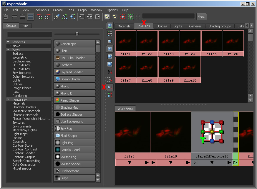
Click
“Texture” tab in Hypershade, and we can see all the
file nodes. It is better to sort the icons by time,
otherwise “file1” is always followed by “file10”. Double-click each icon and
bring up its attribute editor. Change “Image Name” to the corresponding confocal slice image. For example “file10” is going to be
the tenth slice.
3.4
Duplicate the plane
Select
the plane in perspective view. Select Modify->Freeze
Transformation.
Select
Edit->Duplicate Special and click the square instead of the text.
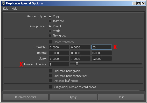
In
the option window, set “Z Translate” to the distance between two confocal slices.
NOTE:
MAKE SURE THIS NUMBER IS CORRECT BEFORE MODELING. THE MODEL WON’T ALIGN IF THIS
NUMBER IS NOT CORRECT.
Set
“Number of copies” to N-1 with N = the number of total Z slices.
Now
the perspective view should look like below.
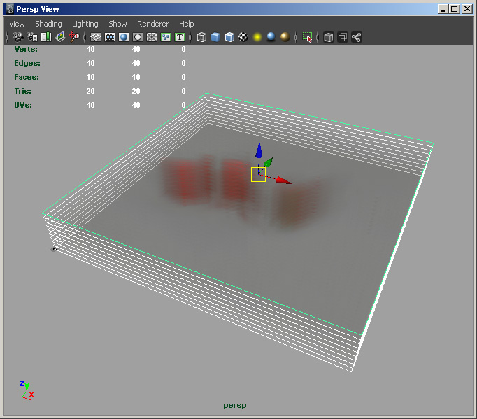
3.5
Assign textures to planes
Now
we should have the same number of surface shader
nodes and planes. Select each plane from the perspective view and assign the
corresponding surface shader in Hypershade.
Then you have implemented a volume renderer for confocal
data in Maya!
USING A SCRIPT: Most of the repetitive work above can be done with Maya’s script
language, MEL. If you happen to know Python, you can also use it to automate
the job. For your convenience, a MEL is provided and you can download it here. To run the
script, copy its code to Maya’s “Script Editor”, read the code and make sure
you understand, modify the variables in the code, and click “Execute All”
button in the toolbar. You still need to set far clip plane of the perspective
camera and the texture resolutions. Refer 3.6 for setting texture resolutions.
Example of settings:
int $isizex=2765;//width
of one z slice(unit=pixels)
int $isizey=4506;//height
of one z slice(unit=pixels)
float $fspcz=16;//space between two
neighboring z slices(unit=pixels)
int $iznum=29;//total
number of z slices
3.6 Manually increase texture resolution
Open Hypershade by
selecting Windowà Rendering Editorsà Hypershade
Select first surface shader node. Double click the node to open Attribute Editor.
Go to Hardware Texturing, and then select Texture Resolution. For muscles, we
use the highest available setting (256x256). Select surface shader
nodes one at a time and change the Texture Resolution. For tendons and nerves,
we make the resolution even higher (Windowà General Editorsà Attribute Spread Sheet;
The last column is Resolution. We set this to 1024 for tendons and nerves).
NOTE: increasing the texture resolution consumes
more graphics memory. Keep the settings low if you are using low-level graphics
cards.
3.7 Group the stacked confocal
images
Open Outliner by selecting Windowà Outliner. Then select
all planes in the Outliner. To group the selected planes, select Edità Group.
Open Channel Box/Layer Editor, under the Display
tab of the Layer Editor, create a new layer and rename the layer “Confocal” (or whatever you choose).
4.
Create a prototype muscle
In this example, we will create a spindle-shaped
muscle, which is used as a prototype for further modeling of different muscles.
4.1 Creating a rough model
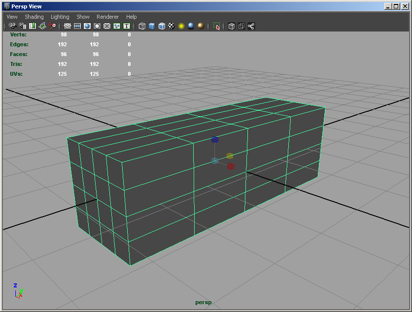
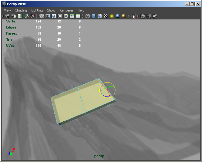
Create
a polygon cube. Set its XYZ subdivisions to 4. Scale properly and make it look
like above.
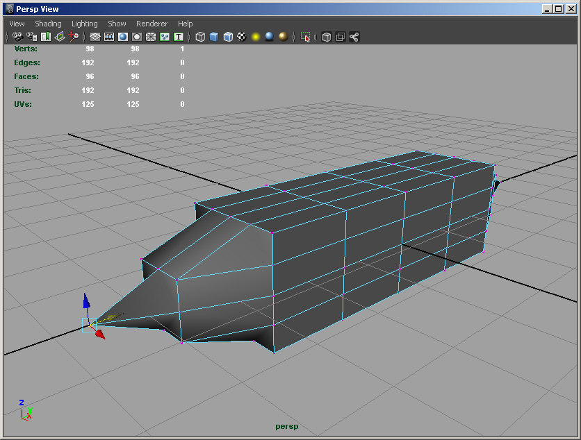
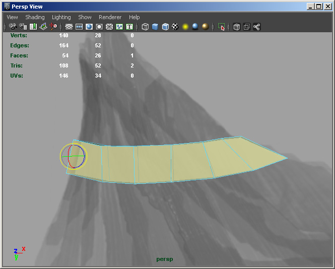
Right-click-and-hold
on the cube until the marking menu shows up. Select “Vertex”
to go to the component mode. Move the vertices of its two ends and make
a shape as above.
4.2
Smooth the model
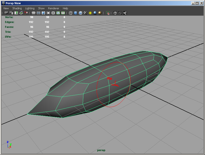
Select
the object from the marking menu. Make sure the menu set is set to “Polygons”.
Then select Mesh->Sculpt Geometry Tool, and choose “Relax” as the Operation
under “Sculpt Parameters” of the Tool Settings. Adjust the brush radius to a
proper value and paint on the cube mode. Smooth angular edges and make them
smooth as above.
4.3
Create UVs
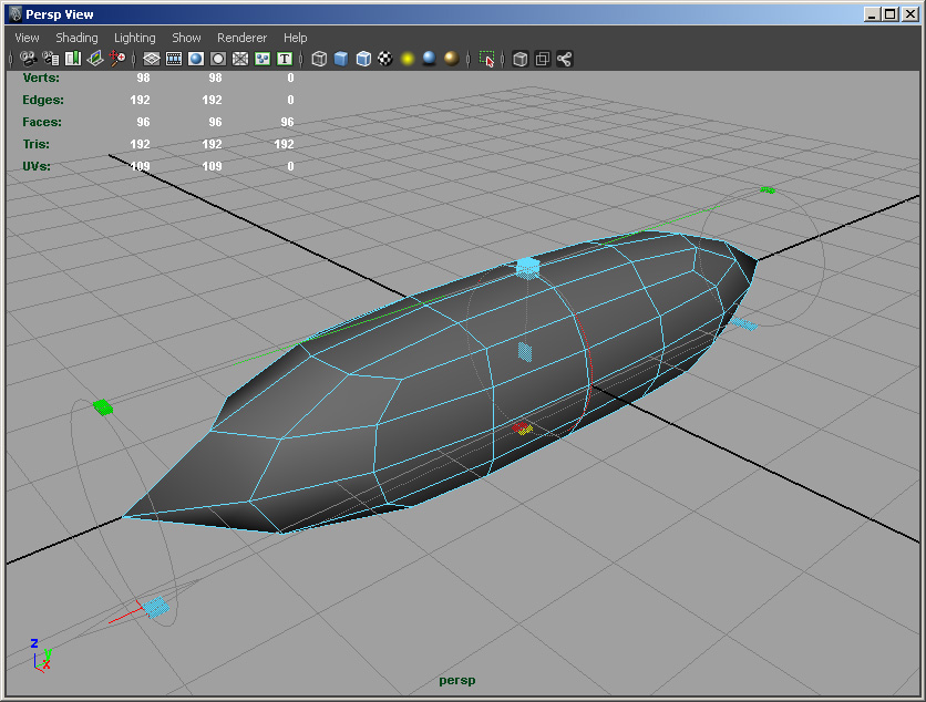
Make
sure the menu set is set to “Polygons”. Select Create UVs->Cylindrical Mapping. Modify the cylindrical
mapping gizmo and make it look like above.
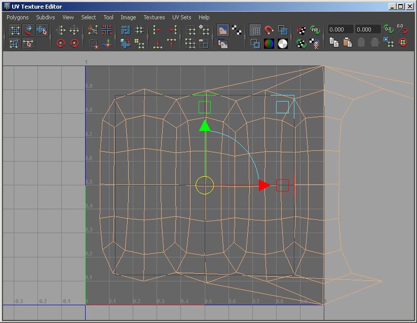
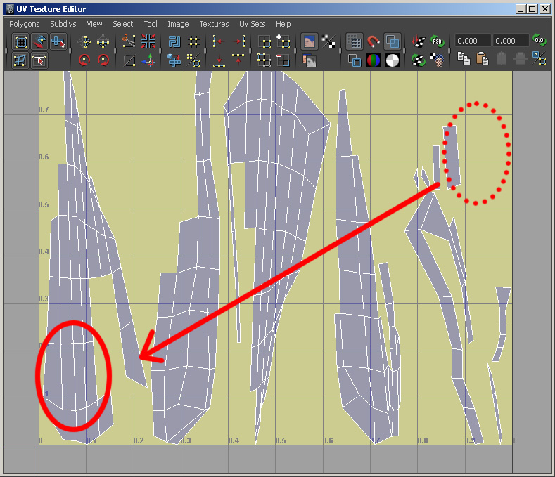
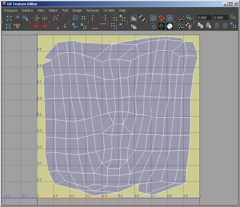
Select
Window->UV Texture Editor and open the texture editor.
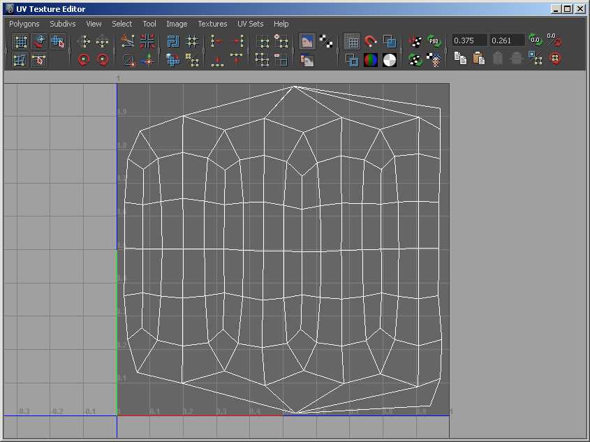
Select
“UV” from the marking menu and fix the UV as above.
4.4
Convert the model to Subdiv
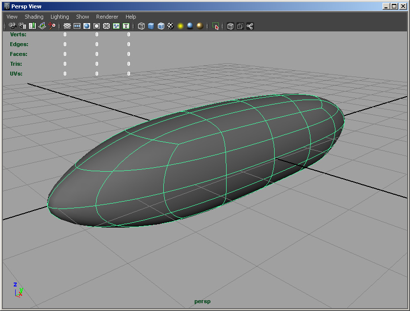
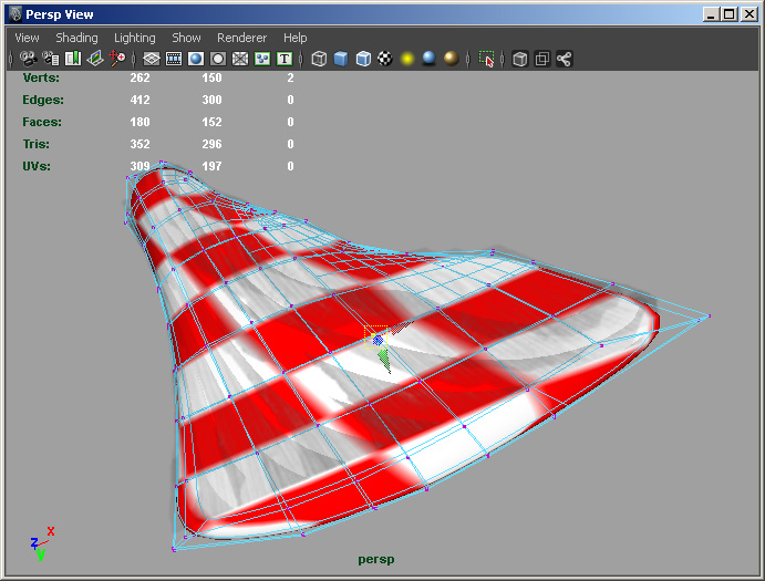
Go to object mode again and select
Modify->Convert->Polygons to Subdiv. Hit “3” on keyboard. It is now smoothed as above.
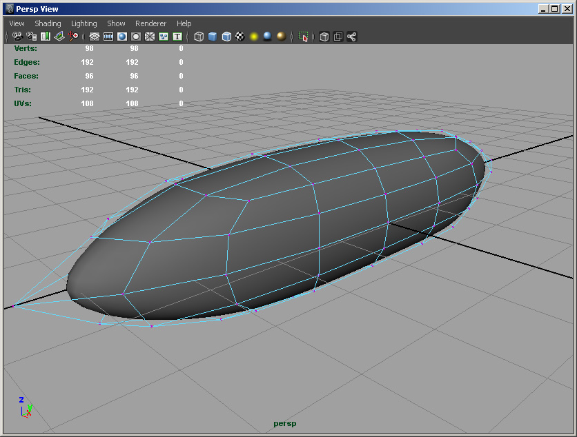
Use
the marking menu can choose “Polygon”. Then use the marking menu again and
choose “Vertex”. It should look like above. The prototype muscle has been
created.
NOTE:
A prototype model can be downloaded here (if you have a
Maya of version earlier than 2012, try this one).
Use
the prototype model for spindle-shaped muscles. Import the prototype muscle
into the volume renderer generated in Section 3. It may be too small compared
to the planes. Scale, rotate and translate it to fit the reference image. Tweak
the vertices and model its shape.
5.
Modeling structures of general shapes
For
structures that can’t be easily modeled from the prototype muscle, we use more
general modeling approaches. Here is an example of modeling a muscle from a
box.
5.1
Create a box
Create
a polygon cube. Keep its XYZ subdivisions to 1. Translate, rotate, and scale
the box to cover just part of the muscle.
Go
to vertex component mode. Move the vertices of the box so that matches the part
of the muscle it covers.
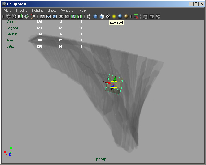
5.2
Extrude the faces of the box
Right-click-and-hold on the object. Select
Faces.
To extrude the selected face, select Edit Meshà Extrude.
Select the Move tool from the toolbar on the
left side of the screen.
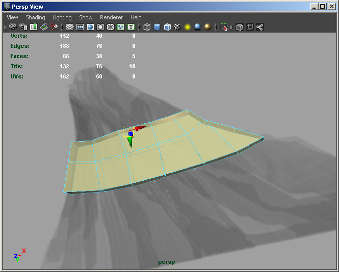
Repeat extruding faces until your polygon model
approximates the confocal rendering.
Making the model more transparent can help with
modeling. You can do so by first go to Windowà General Editorsà Hypershade,
then select the shader of the model. Set the
transparency of the shader in its attribute editor.
Delete the histories on finishing the model. To
delete history, select Edità Delete by all typeà History. The history
will no longer appear in the Channel Box/Layer Editor.
6. UV unwrapping and finalize the model
6.1 Unwrap UVs
To apply a texture onto a polygon model, you
must first unwrap the existing UVs. UVs, or texture
coordinates are generated by projecting the vertices of the polygon model to a
2D plane. Here we use Maya’s Automatic Projection first and stitch the UVs together.
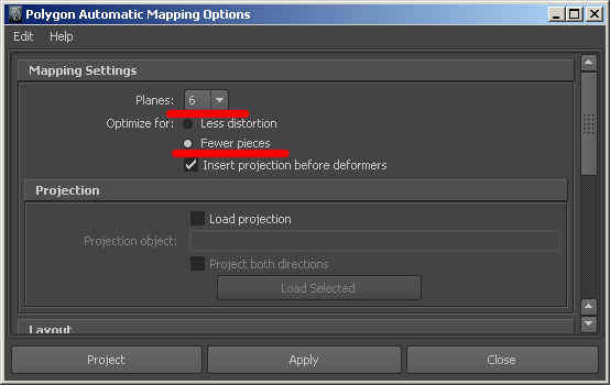
For an Automatic Projection: Go into object mode
and select the object. Then select Create UVsàAutomatic Projection,
select 6 planes, which will create 6 planar projections, and select “Optimize
for fewer pieces”.
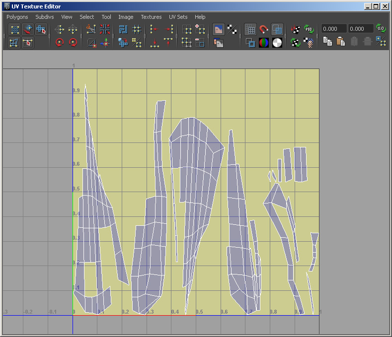
To see the UVs, open
the UV Texture Editor by selecting Windowà UV Texture Editor. The
model will look like a puzzle, and it will need to be pieced back together.
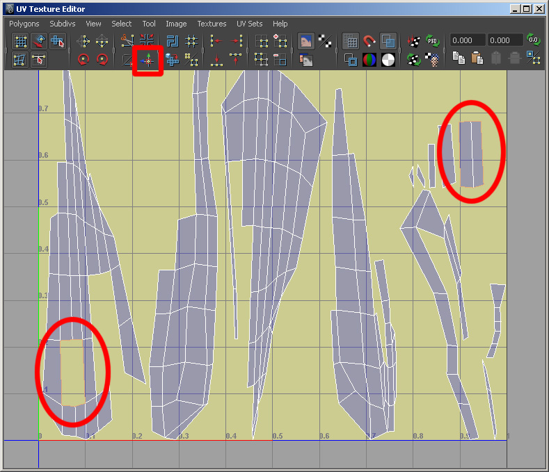
In the UV Texture Editor window, you can select
an edge of one of the “puzzle pieces,” and it will be highlighted, as will its
corresponding edge. Then use the “Move and Sew Selected Edges” button to stitch
together the pieces.
When all the UV pieces are stitched together,
move the stitched together flat model back into the unit square in the window.
Make sure all the UVs are within the range of the
unit square.
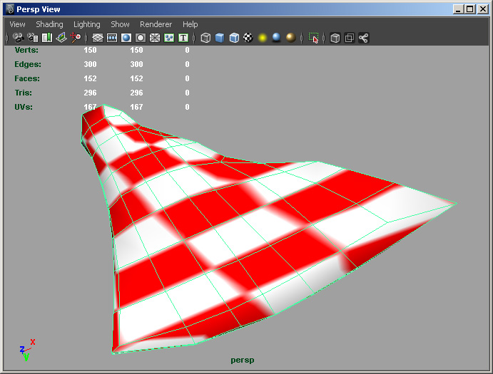
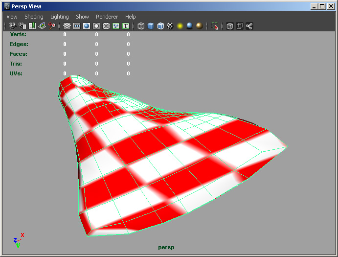
To check the quality of
the UV unwrapping; Windowà General Editorsà Hypershade. Select Lambert, and set
its surface to the checkered pattern and the color to red. Look at the effect
of checkering on the model.
6.2 Convert the polygon model to a subdivision
surface
Select the polygon model and make sure it’s in object
mode.
Select Modifyà Convertà Polygon to SubDiv.
Hit “3” on keyboard. It is now smoothed as
above.
6.3 Fine tuning of model shape
Use the marking menu can choose “Polygon”. Then
use the marking menu again and choose “Vertex”. It should look like above.
Use the vertices to further adjust the model.
7. Texture
7.1 Create texture in Photoshop.
Create a new Photoshop file. Set the resolution
to 2048x2048.
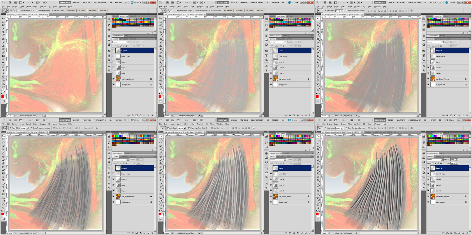
Draw fibers based on volume rendering of the
muscle.
7.2 Export the model from Maya as OBJ
In Maya, select the subdivision surface that we
want to export, and then select Modifyà Convertà SubDiv
to Polygons (Select square for creation options). Set the options to: Uniform
tessellation, Level 3, and then click Convert.
Fileà Export Selectionà Export the OBJ file.
7.3 Paint texture in Mudbox
Open Mudbox.
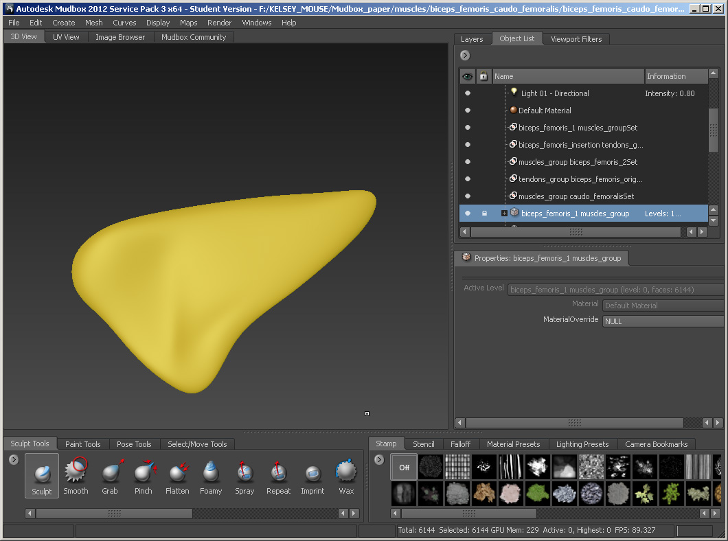
Open OBJ file of model.
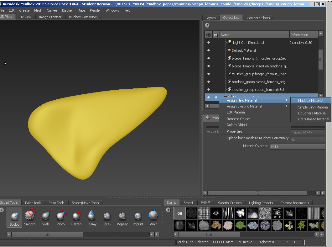
In object list, select the model and right click
on the selection. From the popup menu, select Assign New MaterialàMudbox Material. Now we
created a new material for the model.
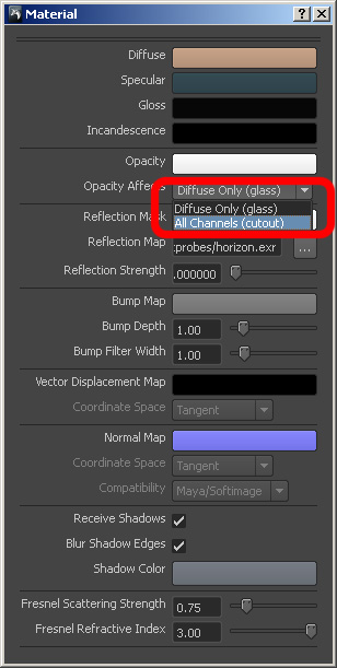
In the material property box, select “All
channels” for “Opacity Affects”.
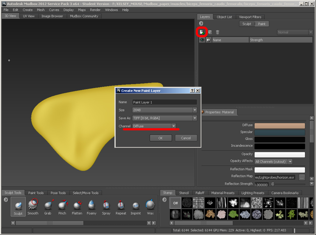
In the Layers panel, select Paint Layers. Click
the “Create new paint layer” button to create a new paint layer. Set the paint
layer type as “Diffuse”.
In the case of limb muscles and tendons, it is
important to paint transparency on tendons (while in Mudbox)
so that the muscle and tendon intersect properly. To create an opacity layer,
do the same as creating the diffuse layer, but choose the paint layer type as
“Opacity”.
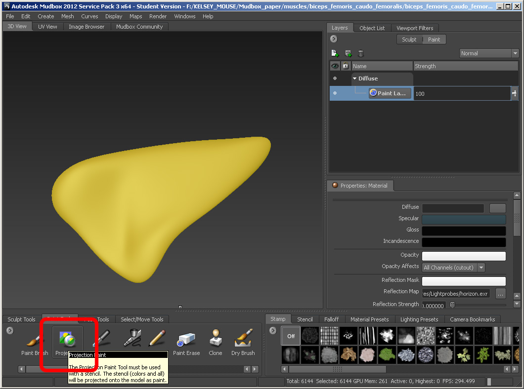
Now we need to use the projection brush to paint
the texture. Select Paint Toolsà Projection.
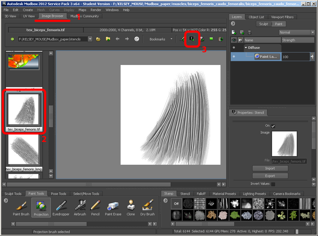
Select the image browser tab and then open the
folder with the texture file in it. Select texture file within Mudbox and click “Set Stencil”
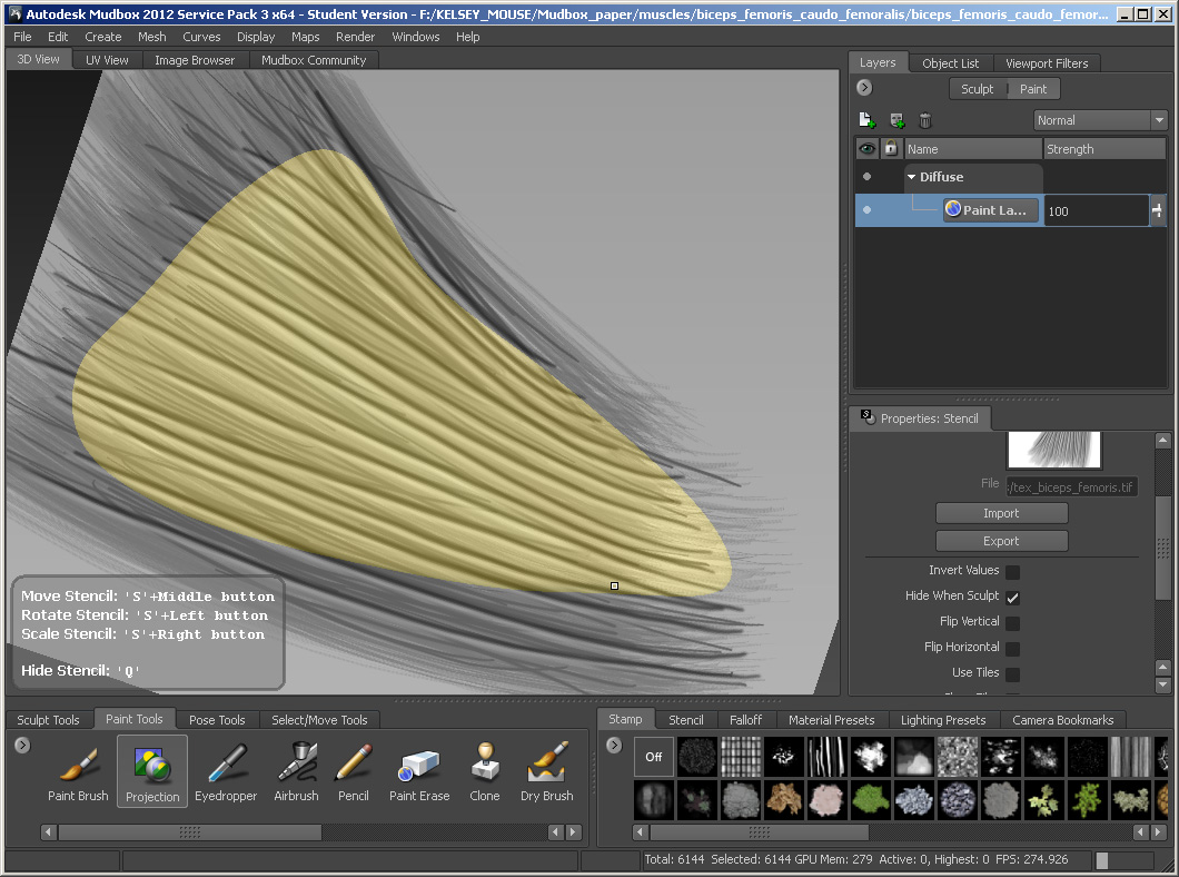
Orient the texture on the model.
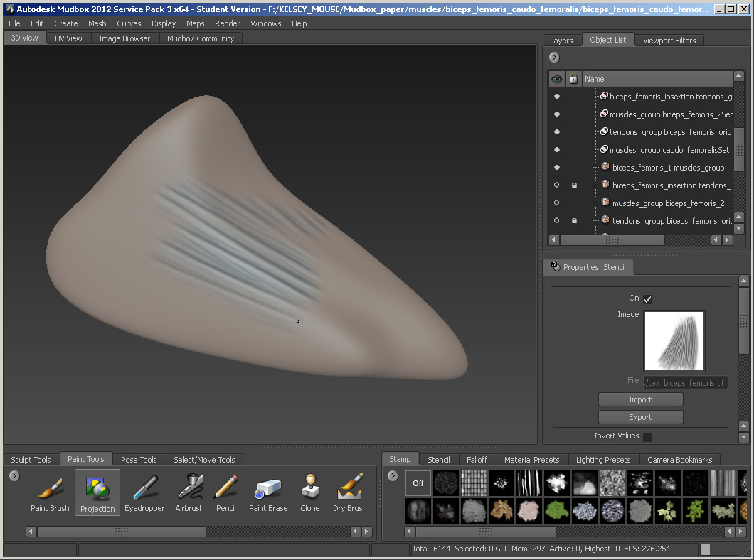
Paint the texture.
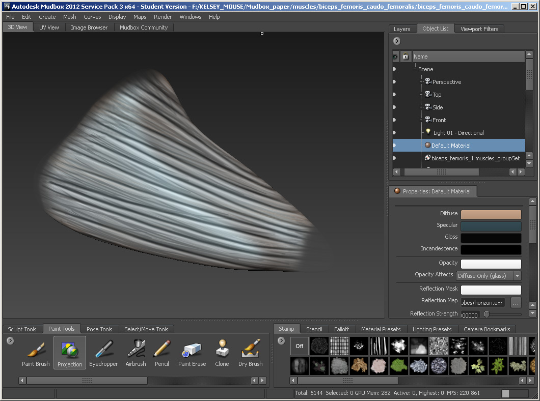
Save the Mudbox
project after painting.
8.
Ready the models for FluoRender
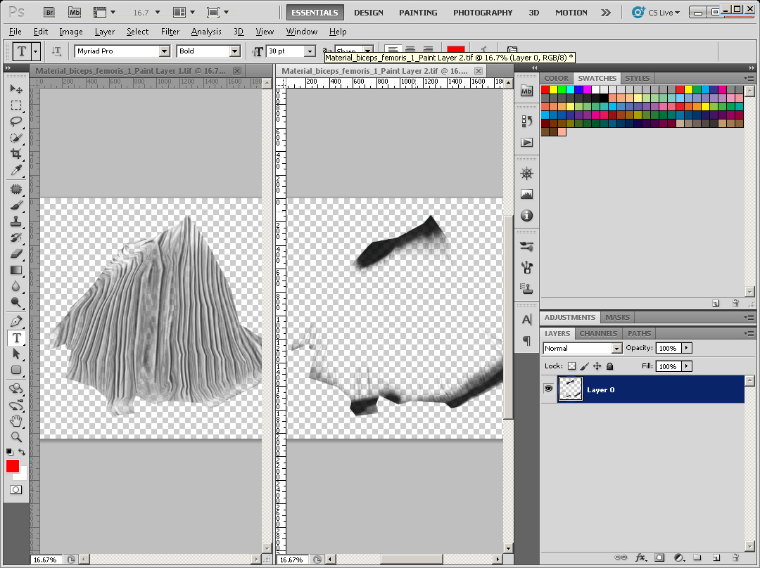
Find
the diffuse and opacity (if present) files within Mudbox’s
project folder, and open them in Photoshop.
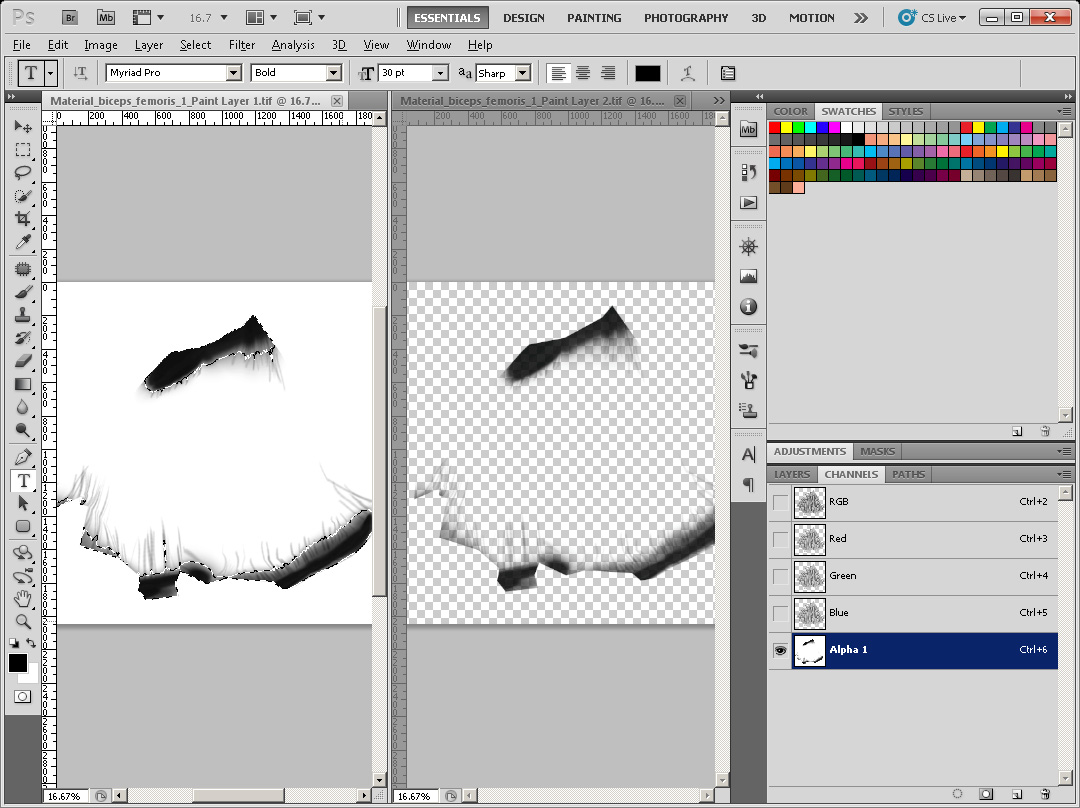
Use
the opacity files as the alpha channel of the diffuse file.
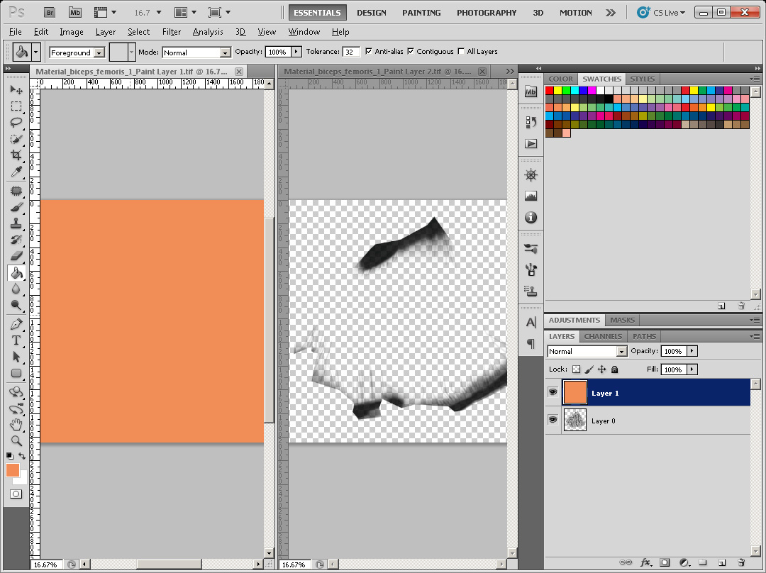
Add
a new layer to the diffuse file. Use the bucket tool to fill a solid color to
the new layer.
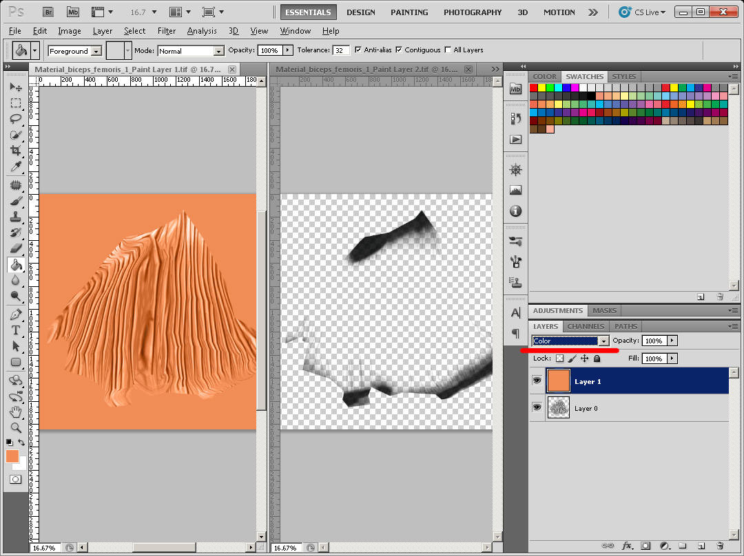
Set
the blend mode of the new layer to “Color”.
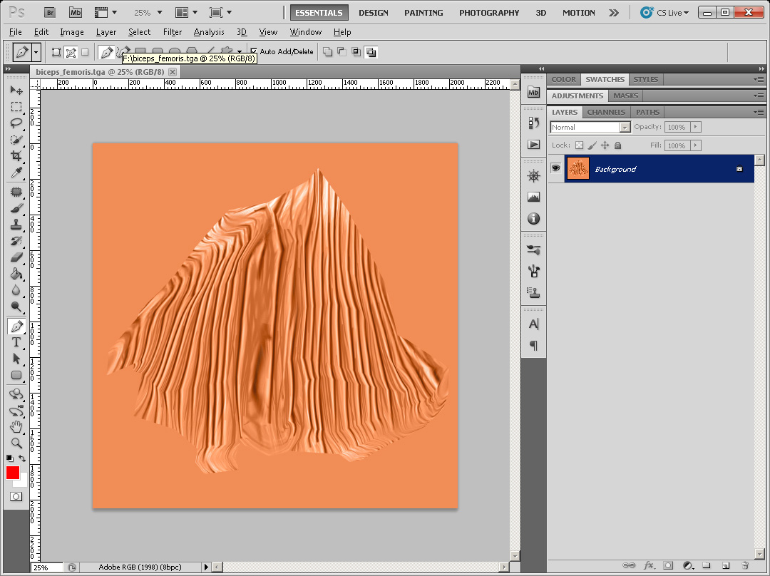
Flatten
the layers and save it as a TGA file.
Put
OBJ, MTL, and TGA files in the same folder. Use a text editor to open the OBJ
file and the MTL file.
Edit
the MTL file as follows:
newmtl lambert
illum 4
Kd 0.00 0.00
0.00
Ka 0.00 0.00 0.00
Tf 1.00 1.00
1.00
map_Kd [the TGA file name]
Ni 1.00
Find the line starting with “usemtl”
in the OBJ file, and replace the material name after to “lambert”.
Now the OBJ file can be opened in FluoRender, with its material and texture properly linked.